A new way of programming Arduino devices
How many times have you used a visual representation to explain your thoughts?
Drawing is often used at planning, it is natural for humans. Even by easy task like navigate someone to a certain place it is easier to use a visual explanation (e.g. map) than text description. When you want to design a software (or let someone to design it for you), you will probably explain your thoughts by drawing some boxes and arrows on a paper. And we want to keep it that way.
Just imagine you draw some boxes interconnect them with lines and after you click on the build button something generates the program for you. Yes, this is exactly what hides behind Project Xenon.
Just imagine you draw some boxes interconnect them with lines and after you click on the build button something generates the program for you. Yes, this is exactly what hides behind Project Xenon.
Users without background in computer science are often intimidated by the syntax and quirks of programming languages. It takes a long time and practice to learn how to express your imagination and thoughts by programming language.
In Project Xenon the boxes are called blocks. These blocks represents some functionality like addition, multiplication, logical expression and so on. The functionality represented by the block is accessible through block inputs and the result is provided on the blocks outputs. As you can guess you are making
programs by interconnecting different blocks by dragging lines from one block's output to another one block's input. These lines are called wires and represents arrows from our boxes and arrows example mentioned above.
For better explanation consider the following diagram. There are four blocks. Two value blocks, one sum block and one display block. By interconnecting these block like in the next image you have created your first program.
 |
 |
Let's add some more math, multiply the output of block Sum by number 4.

Now add some logic: if the result is greater than 5, and less or equal to 9.

But we are running these examples on an Arduino device. The real advantage of Arduino is its ability to communicate with the real world. Let's measure a voltage. You can measure voltage on Arduino by using it's analog inputs. Don't worry, you do not have to code. We will just use a block called analog input. This block provides on it's output a voltage measured on a chosen pin.
To make this example more interesting we will use a part that converts a temperature to voltage: LM35. If you dig a little bit around this part you will learn that by multiplying the measured voltage by 100 you get the measured temperature. And to make a little bit more real world example let's turn Arduino into a cooling device that keeps temperature below certain level.

First we will measure the voltage on analog input number 5. Because there is an output from LM35 connected to this analog input we can convert the measured voltage to degrees by multiplying the value by 100. The display block shows that there is 21.9° Celsius inside the room we are working.
Then we add two conditions. We want to start a fan after the measured temperature goes above 30.0° Celsius and turn off the fan after the temperature goes below 25.0° Celsius. By connecting these conditions to a RS block (see RS Flip-flop) we are able to create required condition to drive the fan.
But, Arduino can't turn on a fan by itself. It doesn't have enough power. So we have to use an Arduino Motor Shield to turn on a fan. We have connected the fan to the ,,A" output of the motor shield . This output can be turned on by setting logic one on Arduino's digital output 3 and turned off be clearing the same output. And at least we will add a Live Scope block to the diagram. We provide a measured temperature and logic condition that drives the fan to this block. This way we will be able to watch the regulation process in real-time.
 |
 |
 |
As you can see, visual programming language lowers the entry barrier for non-programmers. Everything works in a simple drag&drop way. You can manipulate the block parameters in an user-friendly way, with customized help and live previews. So you know what's going on. Now we would like to introduce some features of Project Xenon. The detailed description will be covered in following articles.
Remote development target
We didn't end up in the middle of the journey. The ability to generate a working program from a diagram is awesome. But that is only the half of the story. After we generated the first program we realized that we want to play a little bit with the result. We want to watch exactly what going on. Or we wanted to change some variables inside a running program. Therefore we developed three special blocks: value, display and live scope.
The value block provides on its output value you have entered. If you connect to a running program you are able to change this value in real-time. So if you want to fine-tune some values you do not have to reprogram the device over and over again. Everything you have to do is just simply double click on a block you want to change a enter a new value.
The display block is a simple block with one input. It read the value four time a second and display it directly in the diagram. You saw these block in the first examples. Now you now that you are able to change the value any time you like and see the response directly in the diagram.
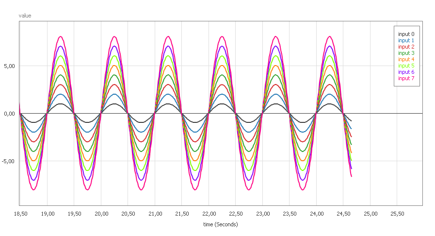
The ,,live scope" block is the most advanced block in remote target library. It can reads up to eight values at a time and send them as fast as possible back to diagram. You can connect to any ,,Live Scope" and see the data at real-time. You are able to have unlimited scopes in the diagram. The following images show the generation of eight sine waves and the data obtained through ,,Live Scope".
 |
 |
The ability to quickly connect a scope to a wire and see what's going on makes the development extremely fast. You can connect to any wire in the diagram. You are able to change the value of the value in the diagram in real-time. This way you can control, setup and test your solution without any need of reprogramming and running the device again.
Just imagine the last time you ware fine-tuning your solutions. How much time did you spend on it? Now you are able to fine-tune your solution and watch it's response in scope.
Generator and Sine Source
Many times we found ourselves in a situation where we had to produce a signal with a specific shape. It's hard to create and fine-tune signal shape by code. It requires a lot of math and it is a very time consuming process. We wanted to simplify this process as much as possible. So we simplified it to a drag&drop level.
But first to demonstrate this feature we will connect Arduino to a R2R DAC (Digital to Analog Converter) and watch the signal on an oscilloscope. In the following image is an Arduino connected to a R2R network. The output of the R2R network is then connected to an oscilloscope probe.

The individual bits of R2R network are connected to digital outputs 41,39,37,35,33 and 31. We have to spread the generated signal among these digital outputs. The whole diagram of generated signal spread among digital outputs is on the fallowing image.

First we generate the signal by ,,Generator" block. Then we convert it by ,,Convertor" block to values from 0 to 255. Then we connect this data to a block that will split them into bits ,,UINT8 to Bits" and we connect the results to appropriate pins.
We have set up the ,,Generator" block as depicted on the following image. The data varies from 0.0 to 1.0 according the shape we entered by simply moving/adding points. And we set the period of generated signal to 1000 ms.

The result observed by the oscilloscope:

Now if we would like to change the shape all we have to do is to move/add/remove points of the shape. No math or programming required.
The next type of generator is especially suitable when you want to create a sine wave with variable frequency and offset. And even if you want a smooth transition from one frequency to another. Again, we connected Arduino to a DAC to see the signal on an oscilloscope.

The ,,Extended Sin source" generates on it's output data representing a sine wave according the input data. We connected a potentiometer to Arduino's analog input 1. So we can vary the voltage from 0.0 to 5.0 Volts. By connecting an ,,Analog Input" block to ,,Extended Sin source" block frequency input we are able to generate sine wave from 0.0 to 5.0 hertz. The result is depicted on the following image.

Control library
By using Arduino to control some advanced control system e.g. quadcopter you will certainly end up by using this library. It contains all the blocks required to turn Arduino into an advanced control systems e.g. transfer function, integration and derivation.
 |
 |
We will describe this library in later articles.
Digital I/O, Analog In, Servo Out, PWM Output
The basic application of Arduino is to comunicate and interract with its environment, with the world. Arduino supports many ways to interact with the environment. So we wrap Arduino features into several easy to use blocks. You can turn on LEDs, react to button push, read analog values, control servo motor and drive PWM. Just by combining these blocks with simple logic you are able to create powerful applications.
I2C/SPI protocol generator
This feature belongs to one of our greatest inventions. By entering just a single line, the description of I2C protocol, the environment generates all the stuff needed to communicate with I2C device. You do not have to study all the functionality, registers, interrupts and bother with its implementation to suite your needs. All you have to do is to describe the communication protocol and provide required data you want to send.
You are even able to split complicated protocols into several easy to understand parts and run then sequentially. The following diagram shows initialization and communication with a MPU 6050 device.

The data obtained from MPU 6050 are shown on image below.
 |
 |
You are not limited to only one device, you are able to communicate with as many devices as you want. The one and only thing you need to learn is the protocol used to interact with I2C slave device.
Conclusion
We put a great effort into this project. Now we want to hear your feedback. There is a lot of awesome functionality we don't mentioned in this article (e.g. creating groups, running groups on a pin interrupt, measuring impulse length and so on). We believe that thanks our project more and more people will be able to became a part of an awesome Arduino community.
No comments:
Post a Comment